50KV30m Rubber Gloves test set (1 pair)
Product Details:
- Dimension (L*W*H) Approx. Dimension : Control & Measurement Unit : L=508mm X W=394mm X H=280mm AC HV Transformer Unit : L=407mm X W=432mm X H=610mm Insulated Test Bath Unit L=256mm X W=381mm X H=737mm Millimeter (mm)
- Weight Approx. Weight : Control & Measurement Unit : 29.100 Kgs. AC HV Transformer Unit : 52.600 Kgs. Insulated Test Bath Unit : 6.200 Kgs. Kilograms (kg)
- Click to view more
50KV30m Rubber Gloves test set (1 pair) Price And Quantity
- 160000 INR/Unit
- 1 Unit
50KV30m Rubber Gloves test set (1 pair) Product Specifications
- Approx. Weight : Control & Measurement Unit : 29.100 Kgs. AC HV Transformer Unit : 52.600 Kgs. Insulated Test Bath Unit : 6.200 Kgs. Kilograms (kg)
- Approx. Dimension : Control & Measurement Unit : L=508mm X W=394mm X H=280mm AC HV Transformer Unit : L=407mm X W=432mm X H=610mm Insulated Test Bath Unit L=256mm X W=381mm X H=737mm Millimeter (mm)
50KV30m Rubber Gloves test set (1 pair) Trade Information
- All India
Product Description
Technical Features :
Input : 230volts + 10%, 50 Hz, 1 Phase AC.
Output : Continuously variable 0 to 50 KV AC.
Current at HT side : 30mA max.
Capacity : 12KVA max.
Duty : Intermittent ie. 5 mins. ON, 10 mins. OFF.
Over load Tripping : In case of electrical breakdown of gloves.
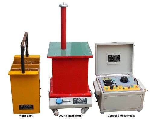
The above test kit will be in 3 units i.e.
1.Control & Measurement Unit.
2.AC HV Transformer.
3.Insulated Test Bath Unit.
All the above units will be provided with wheels for easy movement.
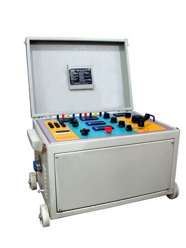
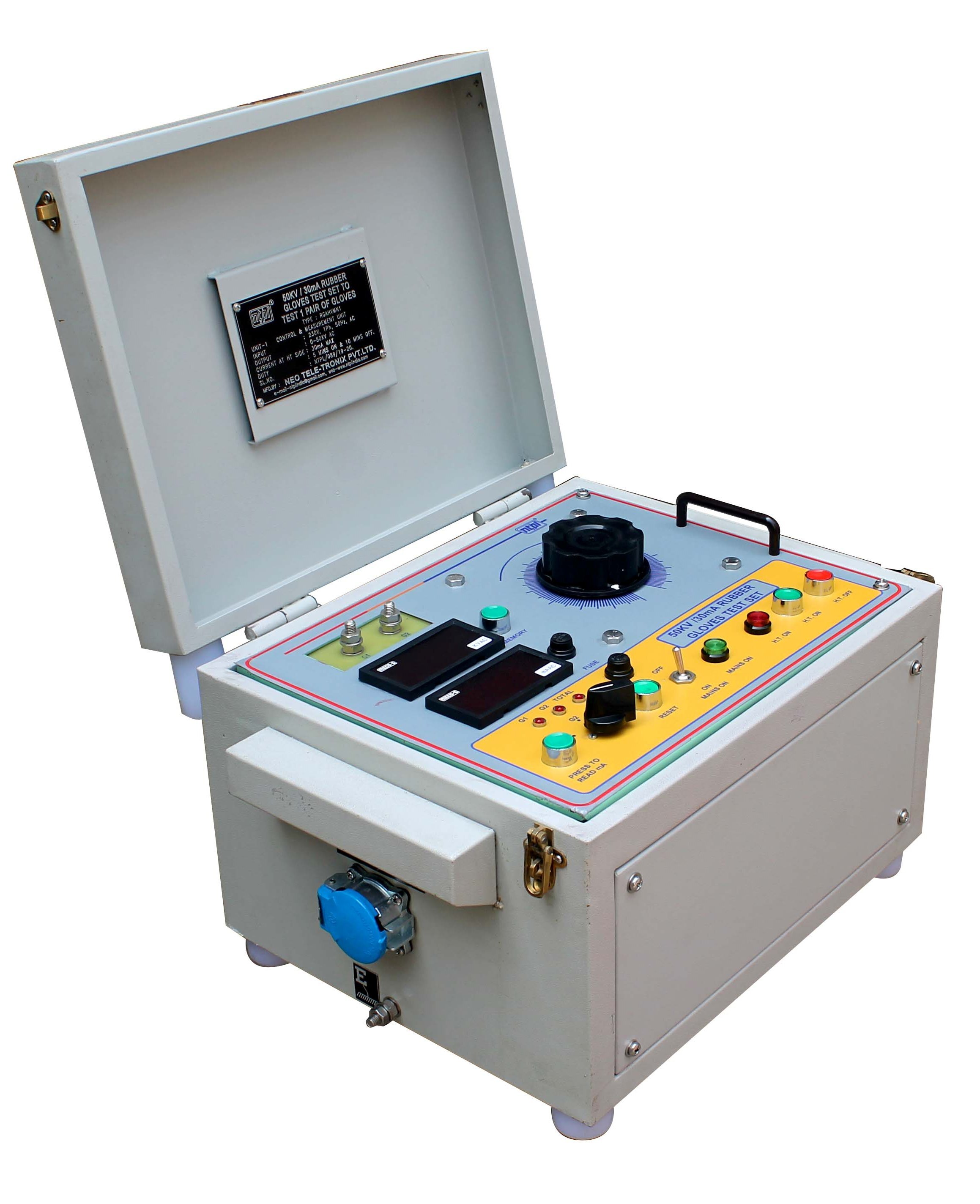
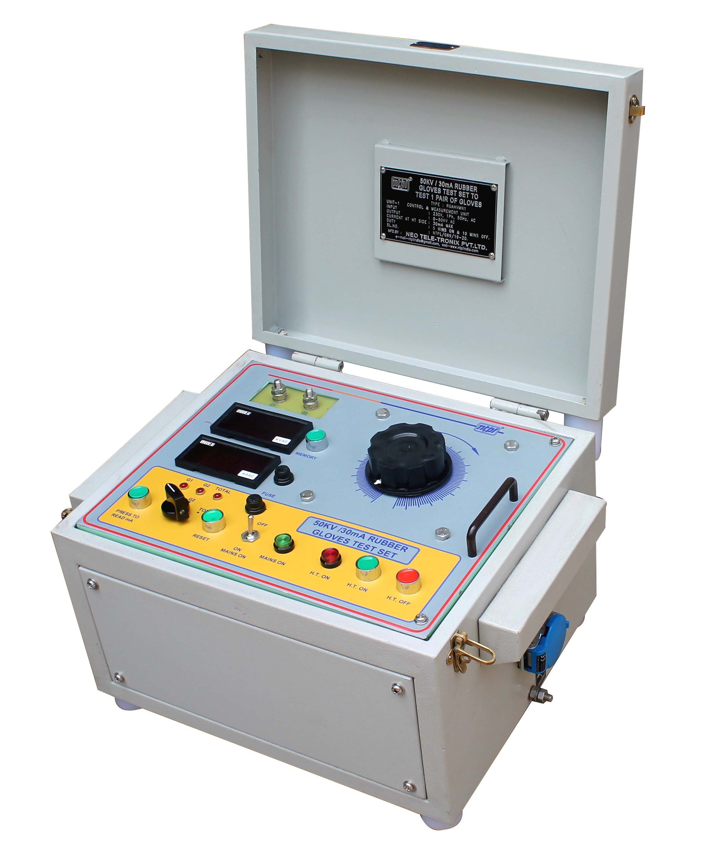
Control & Measurement Unit :
Power Mains ON OFF operation is done by means of an ON-OFF switch along with MAINS ON lamp indication & Fuse. HT ON-OFF push button along with HT ON lamp indication. Continuously variable autotransformer of suitable capacity to increase/decrease the output test voltage up to the required voltage level.
Zero start interlock will be provided to ensure that the HV circuit cannot be energised unless the regulator is initially kept or brought back to zero position.
Automatic tripping mechanism for protecting the HV transformer against over loading. Tripping mechanism can be adjusted at 15mA for individual Gloves test and the total capacity for 1 pair gloves at a time is 30mA. After tripping, High Voltage will be switched OFF. This protective device will be provided with latched circuit to indicate the defective gloves. Lamp corresponding to the defective gloves will glow as indication
Digital voltmeter generally connected to the LT side for HV measurement and scaled in KV.
Digital milliammeter along with Press to read mA push to read the leakage current.
In case the output voltage crosses the maximum rated value a lamp & a buzzer will indicate over voltage.
Memory device enables the meter of the Test Set to indicate the breakdown voltage by pressing the Memory push button even after the high voltage circuit is tripped OFF.
The whole control circuitry will be housed within a sheet metal cabinet treated properly and powder coated.
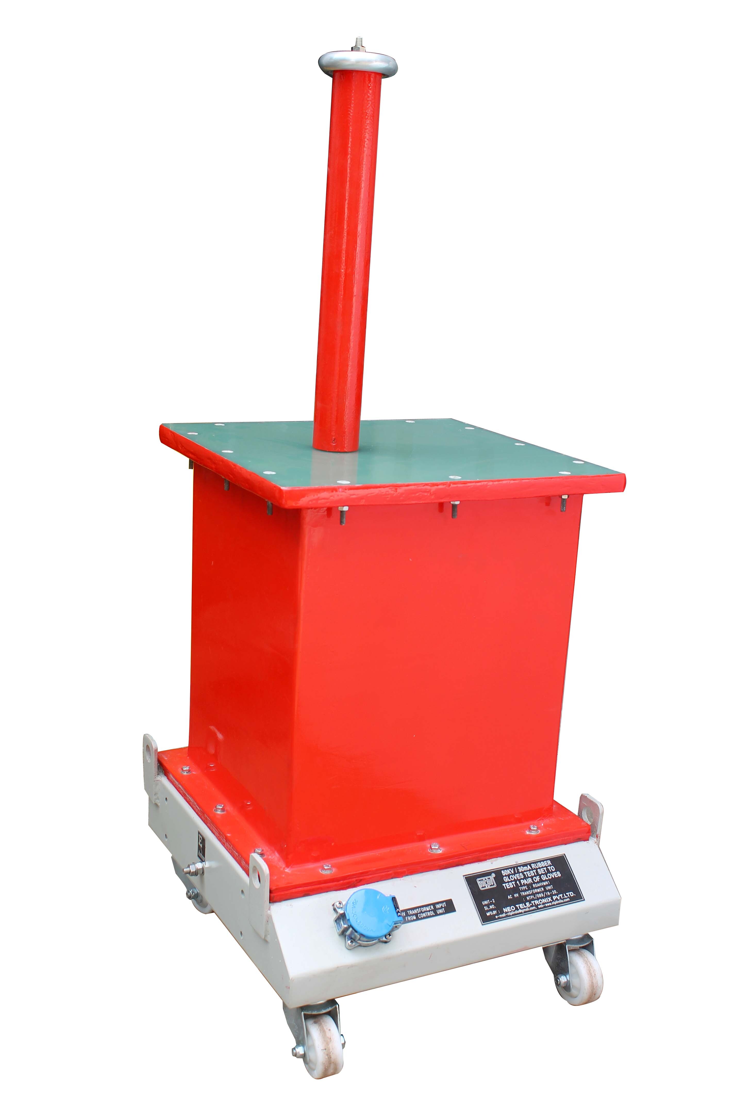
HV Transformer :
HV Transformer used in the test set will be cast resin dry type and of suitable capacity. The HV winding of the Transformer is of graded insulation; one end being connected to the earth potential while the other end remains in floating condition as HT Terminal.
The transformer will be designed to withstand frequent intermittent spark over or short circuit conditions under which such testing transformers are designed to operate.
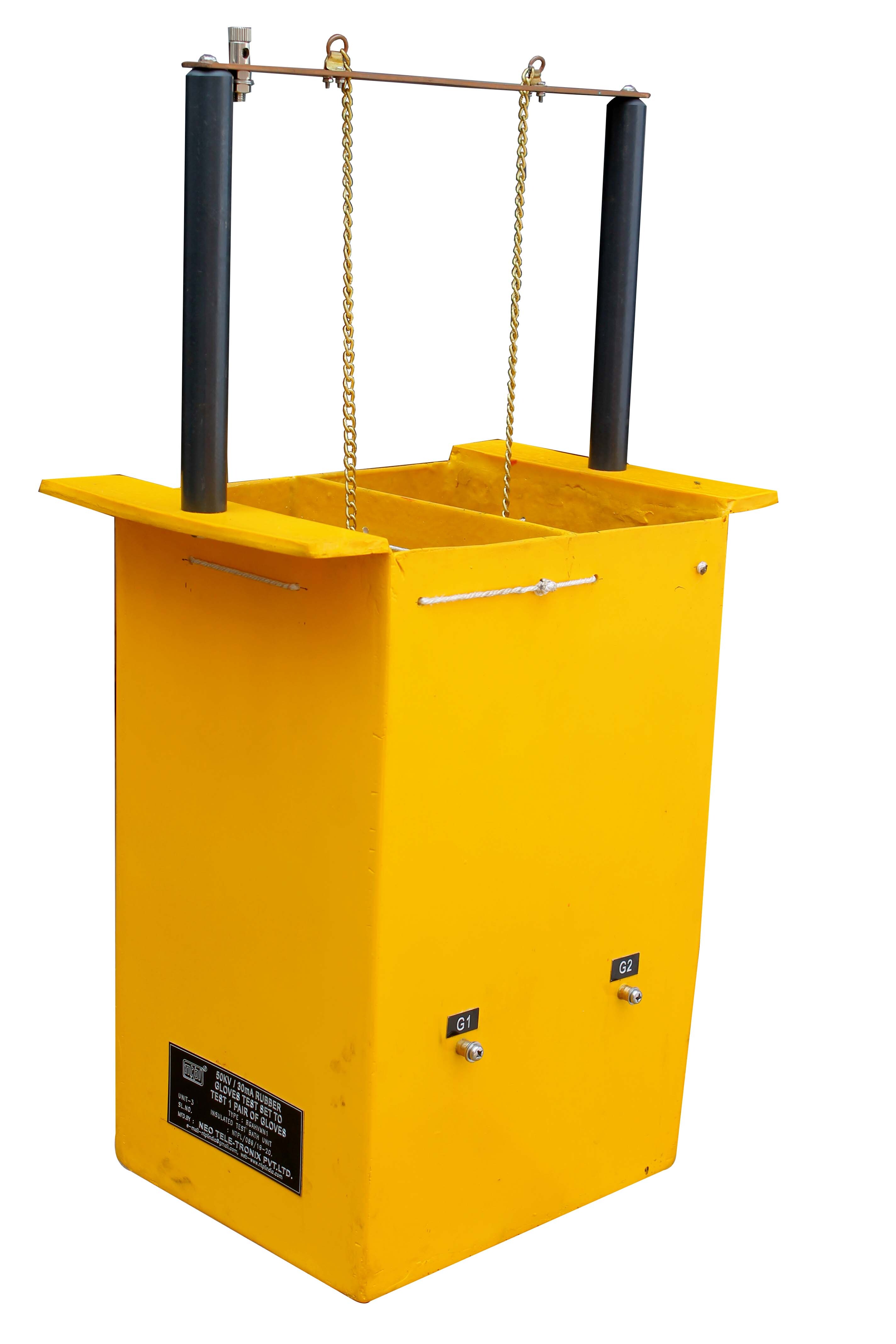
Insulated Test Bath Unit :
The insulating bath unit will have 2 nos. of test chamber isolated from each other by insulating wall. Each individual test chamber will be provided with arrangement to hang gloves under test with insulating string grid. A conducting rod is arranged in such a way that one pair of electrode chain fitted to this conducting rod, remains dipped in water within the Gloves. Grounding electrodes are fitted with each test chamber filled with water. The conducting rod with chain electrode will be connected to the HV end while Grounding electrodes will be connected to earth potential through metering circuit & tripping device.
Interconnecting Cables :
Interconnecting cables of approx. 3 meters length are to be provided for interconnection between the units.
Documents :
The following documents will be provided along with the test set.
Operation Manual.
Works Test Report with traceability.
Warrantee Certificate.
Approx. Dimension :
Control & Measurement Unit :
L=508mm X W=394mm X H=280mm
AC HV Transformer Unit :
L=407mm X W=432mm X H=610mm
Insulated Test Bath Unit
L=256mm X W=381mm X H=737mm
Approx. Weight :
Control & Measurement Unit : 29.100 Kgs.
AC HV Transformer Unit : 52.600 Kgs.
Insulated Test Bath Unit : 6.200 Kgs.

Price:
- 50
- 100
- 200
- 250
- 500
- 1000+
Other Products in 'Electrical Testing Equipment' category
Works:
117, Mishrapara Road, Rathtala, P.O. Rajpur,
Kolkata - 700 149, West Bengal, India.


