100KV100mA AC HV Test set
Product Details:
- Measuring Voltage Range Continuously variable from 0 to 100 KV. Volt (v)
- Dimension (L*W*H) Approx. Dimension : Control & Measurement Unit : L=838mmXW=470mmXH=495 mm HV Transformer : L=584mmXW=533mmXH=890mm Capacitive Potential Divider : L=910mmXW=910mmXH=1230mm Millimeter (mm)
- Weight Approx. Weight : Control & Measurement Unit: 42Kg. HV Transformer: 222Kg. Capacitive Potential Divider: 25kg Kilograms (kg)
- Click to view more
100KV100mA AC HV Test set Price And Quantity
- 1 Unit
- 252000 INR/Unit
100KV100mA AC HV Test set Product Specifications
- Approx. Weight : Control & Measurement Unit: 42Kg. HV Transformer: 222Kg. Capacitive Potential Divider: 25kg Kilograms (kg)
- Continuously variable from 0 to 100 KV. Volt (v)
- Approx. Dimension : Control & Measurement Unit : L=838mmXW=470mmXH=495 mm HV Transformer : L=584mmXW=533mmXH=890mm Capacitive Potential Divider : L=910mmXW=910mmXH=1230mm Millimeter (mm)
100KV100mA AC HV Test set Trade Information
- All India
Product Description
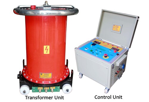
The above test kit will be in 2 units i.e.
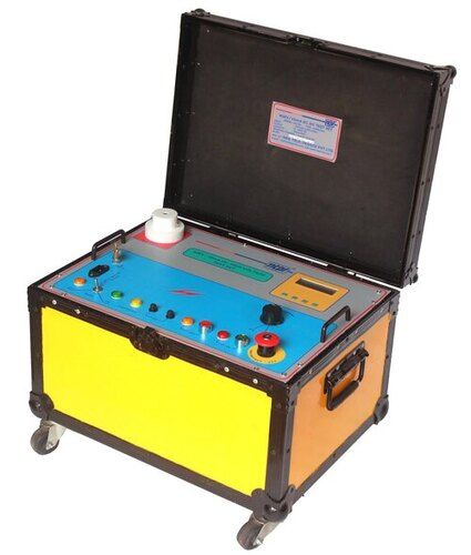
1. Control & Measurement Unit.
2. AC HV Transformer Unit. Power Mains ON - OFF operation is done by means of an ON - OFF switch along with 'MAINS ON' lamp indication & Fuse.
All the above units will be provided with wheels for easy movement.
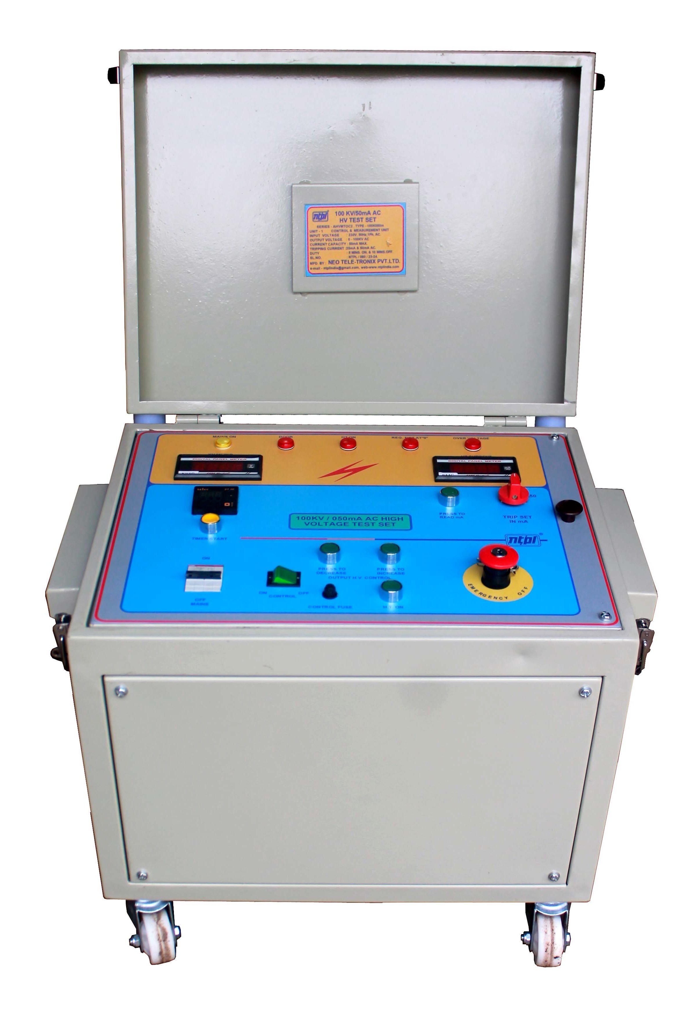
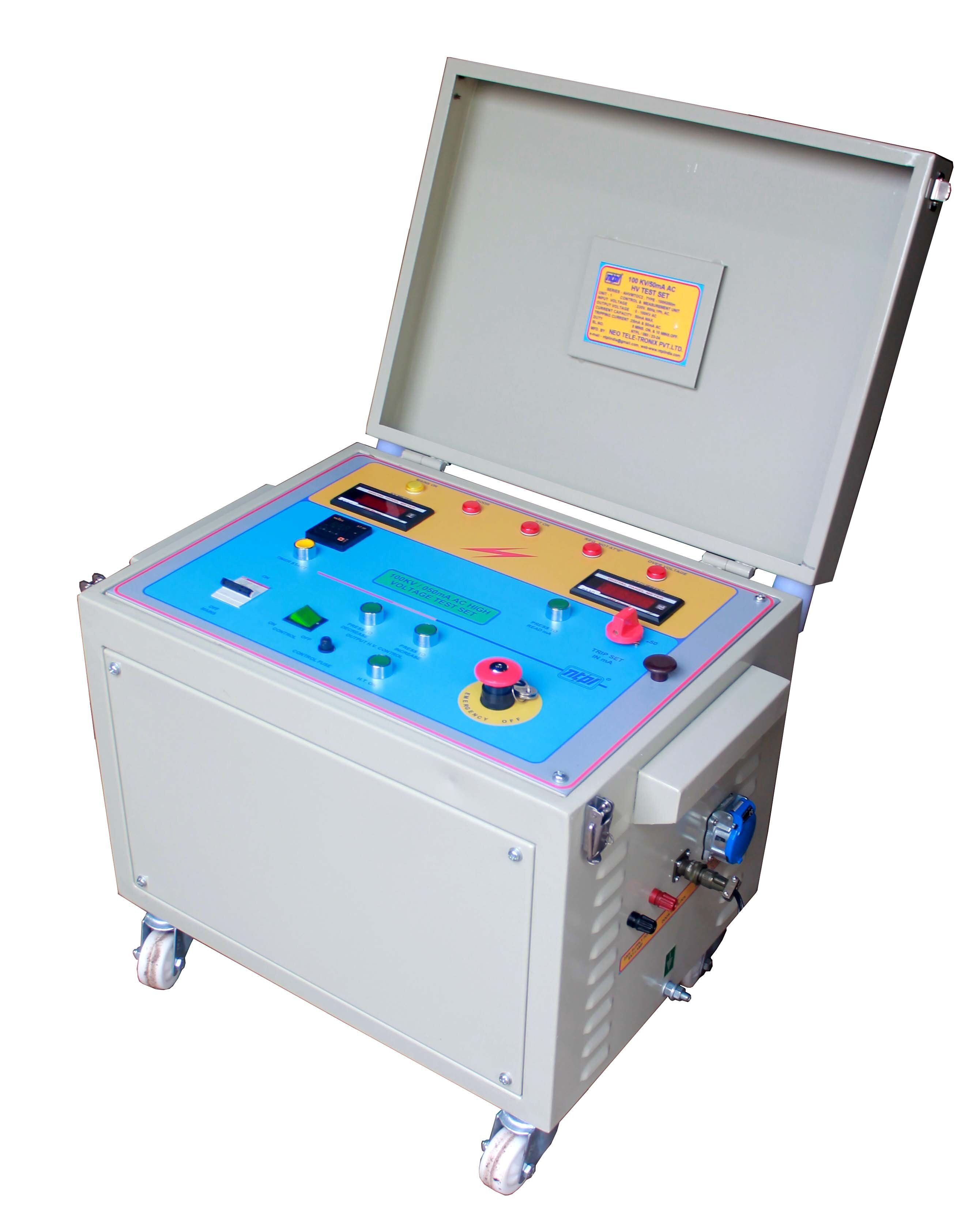
Control & Measurement Unit :
Power Mains ON - OFF operation is done by means of ON-OFF switch & Fuse/ MCB.
Control ON-OFF switch along with fuse protection
'HT ON' push button & 'EMERGENCY OFF' mushroom type push button
Continuously variable autotransformer of suitable capacity to increase/decrease the output test voltage up to the required voltage level.
INCREASE/DECREASE circuit to control motor operated Voltage Regulator. When high voltage circuit is energised the regulator will rotate to
increase the output voltage when 'INCREASE' push is pressed ON or decrease the out put voltage when 'DECREASE' push is pressed ON.
LAMP INDICATIONS: 'MAINS ON, 'HT ON', 'CONTROL ON','REG. NOT AT ZERO', 'OVERVOLTAGE'
Metering :
Digital Voltmeter generally connected to the tertiary winding of HV Transformer and scaled in KV. Resolution: 0.1KV. If Capacitive Potential
Divider is used then the Digital Voltmeter will be connected to the low voltage arm of the HV Capacitive Potential Divider. Resolution: 0.1KV.
Digital milliammeter along with 'PRESS TO READ mA' push button to read the leakage current. Resolution : 0.1mA
A TIMER will be provided to count down the duration of applied HV. After completion of the test time the regulator will automatically decrease
to zero position. 'RESET' feature of the 'TIMER' will be provided.
Interlock :
Zero start interlocking will be provided to ensure that the HV circuit cannot be energised unless the regulator is initially kept or brought back to
zero position.
Minimum & maximum position interlock will be provided so that limit switch will automatically disconnect 'INCREASE/DECREASE' circuit of motor
connection at maximum and minimum position respectively.
Enclosure interlocking will be provided i.e. high voltage circuit cannot be energised unless the door of the enclosure is closed. However, this inter
lock can be by-passed by shorting corresponding terminals.
Protection :
Besides main switch & fuse in the input side/MCB, one CT and contactor provides a snap acting automatic tripping of HV circuit in case of over load.
The tripping mechanism can be adjusted at different values as mentioned above. After tripping, High Voltage will be switched OFF
In case the voltage exceeds the maximum rated value a lamp & buzzer will indicate over voltage. and the increase mode circuit will not function
further, even if 'PRESS TO INCREASE' push is pressed.
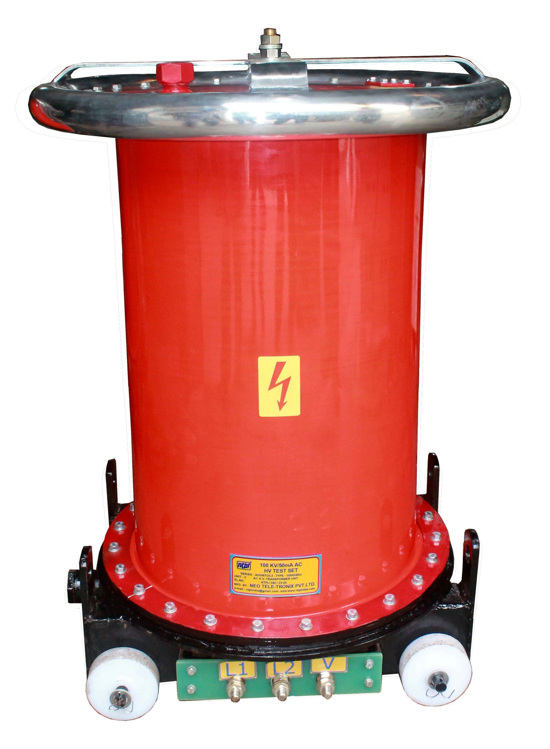
HV Transformer :
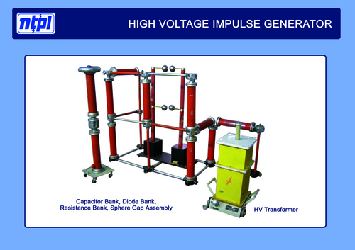
HV Transformer used in the test set will be oil natural cooled indoor type and of suitable capacity.
The HV winding of the Transformer is of graded insulation; one end being connected to the earth potential through a CT operated
milliammeter & tripping device, while the other end remains in floating condition as HT Terminal.
The transformer will be designed to withstand frequent intermittent spark over or short circuit conditions under which such testing
transformers are designed to operate.
HT terminal will be provided with anti-corona metallic ring of adequate diameter to facilitate uniform charge distribution.
The HV Transformer will be mounted on MS trolley within insulated jacket.
Accessories :
The set will be provided with .
I. Power Cable of minimum 5m long - 1 No.
II. Power Interconnector Cable of minimum 5m long- 1 No.
III. Discharge rod with 5M long lead (grounding cable) with clamp- 1 No.
Optional at Extra Cost :
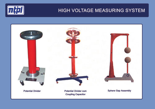
HV Potential Divider :
This is well known that for high capacitive loading the HV output may be more than the expected
voltage i.e. voltage ratio of the transformer. Hence, HV measurement is very vital in this high capacity
AC HV Test set. There will be a capacitive HV Potential Divider provided with low voltage arm.
A UHF connector with co axial cable is used to connect a metering circuit (provided in the panel) to indicate
High Voltage.
Rated max working voltage 100KV AC rms.
The capacitor will be oil-cooled type, provided with corona guard and will be movable with wheels at bottom.
Documents :
The following documents will be provided along with the test set.
Operation Manual.
Works Test Report with traceability.
Warrantee Certificate.

Price:
- 50
- 100
- 200
- 250
- 500
- 1000+
Other Products in 'High Voltage Testing Equipment' category
Works:
117, Mishrapara Road, Rathtala, P.O. Rajpur,
Kolkata - 700 149, West Bengal, India.




 Call Me Free
